Searching...
Saturday, 29 October 2011

SOLUTIONS TO TRANSMISSION PROBLEMS


This section describes some solutions to the problems described in previous sections. Although many of these do not entirely solve all problems on the radio transmission path, they do play an important part in maintaining call quality for as long as possible.

CHANNEL CODING                                                         

In digital transmission, the quality of the transmitted signal is often expressed in terms of how many of the received bits are incorrect. This is called Bit Error Rate (BER). BER defines the percentage of the total number of received bits which are incorrectly detected.


This percentage should be as low as possible. It is not possible to reduce the percentage to zero because the transmission path is constantly changing. This means that there must be an allowance for a certain amount of errors and at the same time an ability to restore the information, or at least detect errors so the incorrect information bits are not interpreted as correct. This is especially
important during transmission of data, as opposed to speech, for which a higher BER is acceptable. Channel coding is used to detect and correct errors in a received bit stream. It adds bits to a message. These bits enable a channel
decoder to determine whether the message has faulty bits, and to potentially correct the faulty bits.


INTERLEAVING                                                              

In reality, bit errors often occur in sequence, as caused by long fading dips affecting several consecutive bits. Channel coding is most effective in detecting and correcting single errors and short error sequences. It is not suitable for handling longer sequences of bit errors. For this reason, a process called interleaving is used to separate consecutive bits of a message so that these are transmitted in a non-consecutive way. For example, a message block may consist of four bits (1234). If four message blocks must be transmitted, and one is lost in transmission, without interleaving there is a 25% BER overall, but a 100% BER for that lost message block. It is not possible to recover from this.

Interleaving


If interleaving is used, as shown in Figure 3-18, the bits of each block may be sent in a non-consecutive manner. If one block is lost in transmission, again there is a 25% BER overall. However, this time the 25% is spread over the entire set of message blocks, giving a 25% BER for each. This is more manageable and there is a greater possibility that the channel decoder can correct the errors.

Received interleaved message blocks

ANTENNA DIVERSITY                                                    

Antenna diversity increases the received signal strength by taking advantage of the natural properties of radio waves. There are two primary diverstiy methods: space diversity and polarization diversity.

Space Diversity

An increased received signal strength at the BTS may be achieved by mounting two receiver antennae instead of one. If the two Rx antennae are physically separated, the probability that both of them are affected by a deep fading dip at the same time is low. At 900 MHz, it is possible to gain about 3 dB with a
distance of five to six meters between the antennae. At 1800 MHz the distance can be shortened because of its decreased wavelength. By choosing the best of each signal, the impact of fading can be reduced. Space diversity offers slightly better antenna gain than polarization diversity, but requires more space.

Space diversity

Polarization Diversity

With polarisation diversity the two space diversity antennae are replaced by one dual polarized antenna. This antenna has normal size but contains two differently polarized antenna arrays. The most common types are vertical/horizontal arrays and arrays in ±45 degree slant orientation. The two arrays are connected to the respective Rx branches in the BTS. The two arrays can also be used as combined Tx/Rx antennas. For most applications, the
difference between the diversity gain for space diversity and polarization diversity is negligible, but polarization diversity reduces the space required for antennae.

ADAPTIVE EQUALIZATION                                            

Adaptive equalization is a solution specifically designed to counteract the problem of time dispersion. It works as follows:
  1. Eight sets of predefined known bit patterns exist, known as training sequences. These are known to the BTS and the MS (programmed at manufacture). The BTS instructs the MS to include one of these in its transmissions to the BTS.
  2. The MS and BTS includes the training sequence (shown in the figure as “S”) in its transmissions.
  3. The other party receives the transmission and examines the training sequence within it. The received training sequence is compared with the known training sequence that is used in this cell. It can be assumed that problems in the radio path affected these bits must also have had a similar affect on the speech data bits sent in the same burst.
  4. The receiver begins a process in which it uses its knowledge of what happened the training sequence to correct the speech data bits of the transmission.


Adaptive equalization


Because some assumptions are made about the radio path, adaptive equalization may not result in a 100% perfect solution every time. However, a “good enough” result will be achieved. A viterbi equalizer is an example of an adaptive equalizer.

FREQUENCY HOPPING                                                   

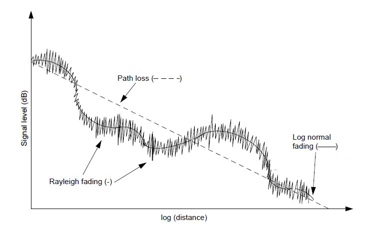
As mentioned previously, Rayleigh fading is frequency dependent. This means that the fading dips occur at different places for different frequencies. To benefit from this fact, it is possible for the BTS and MS to hop from frequency to frequency during a call. The frequency hopping of the BTS and MS is synchronized. In GSM there are 64 patterns of frequency hopping, one of them
is a simple cyclic or sequential pattern. The remaining 63 are known as pseudo-random patterns, which an operator can choose from.

Frequency hopping

During TDMA frame N, C1 is used and during TDMA frame N+1, C2 is used. The call uses the same time slot but changes frequencies according to an identified pattern.

TIMING ADVANCE                                                         

Timing advance is a solution specifically designed to counteract the problem of time alignment. It works by instructing the misaligned MS to transmit its burst earlier or later than it normally would. In GSM, the timing advance information relates to bittimes. Thus, an MS may be instructed to do its transmission by a
certain number of bittimes earlier or later related to previous position, to reach its timeslot at the BTS in right time. Maximum 63 bittimes can be used in GSM systems. This limits GSM normal cell size to 35km radius. However with extended range equipment, distances up to 70Km or even 121Km can be
handled, using 2 timeslots.


Timing advance

TRANSMISSION PROBLEMS


Many problems may occur during the transmission of a radio signal. Some of the most common problems are described below.

PATH LOSS

Path loss occurs when the received signal becomes weaker and weaker due to increasing distance between MS and BTS, even if here are no obstacles between the transmitting (Tx) and receiving (Rx) antenna. The path loss problem seldom leads to a dropped call because before the problem becomes extreme, a new transmission path is established via another BTS.

SHADOWING

Shadowing occurs when there are physical obstacles including hills and buildings between the BTS and the MS. The obstacles create a shadowing effect which can decrease the received signal strength. When the MS moves, the signal strength fluctuates depending on the obstacles between the MS and BTS. A signal influenced by fading varies in signal strength. Drops in strength are called fading dips.

Shadowing

MULTIPATH FADING

Multipath fading occurs when there is more than one transmission path to the MS or BTS, and therefore more than one signal is arriving at the receiver. This may be due to buildings or mountains, either close to or far from the receiving
device. Rayleigh fading and time dispersion are forms of multipath fading.

Rayleigh fading

This occurs when a signal takes more than one path between the MS and BTS antennas. In this case, the signal is not received on a line of sight path directly from the Tx antenna. Rather, it is reflected off buildings, for example, and is received from several different indirect paths. Rayleigh fading occurs when the obstacles are close to the receiving antenna.

Rayleigh fading


The received signal is the sum of many identical signals that differ only in phase (and to some extent amplitude). A fading dip and the time that elapses between two fading dips depends on both the speed of the MS and the transmitting frequency. As an approximation, the distance between two dips caused by Rayleigh fading is about half a wavelength. Thus, for GSM 900 the distance between dips is about 17 cm.

Time Dispersion

Time dispersion is another problem relating to multiple paths to the Rx antenna of either an MS or BTS. However, in contrast to Rayleigh fading, the reflected signal comes from an object far away from the Rx antenna. Time dispersion causes Inter-Symbol Interference (ISI) where consecutive symbols (bits) interfere with each other making it difficult for the receiver to determine which symbol is the correct one. An example of this is shown in the figure below where the sequence 1, 0 is sent from the BTS.


Time dispersion


If the reflected signal arrives one bit time after the direct signal, then the receiver detects a 1 from the reflected wave at the same time it detects a 0 from the direct wave. The symbol 1 interferes with the symbol 0 and the MS does not know which one is correct.

TIME ALIGNMENT

Each MS on a call is allocated a time slot on a TDMA frame. This is an amount of time during which the MS transmits information to the BTS. The information must also arrive at the BTS within that time slot. The time alignment problem occurs when part of the information transmitted by an MS does not arrive within the allocated time slot. Instead, that part may arrive during the next time slot, and may interfere with information from another MS using that other time slot. A large distance between the MS and the BTS causes time alignment. Effectively, the signal cannot travel over the large distance within the given time.


The time alignment problem

For example, an MS is close to a BTS and has been allocated time slot 3 (TS 3). During the call, the MS moves away from the BTS causing the information sent from the BTS to arrive at the MS later and later. The answer from the MS also arrives later at the BTS. If nothing is done, the delay becomes so long that the transmission from the MS in time slot 3 overlaps with the information which the BTS receives in time slot 4.

COMBINED SIGNAL LOSS

Each of the problems described above occurs independently of each other. However, in most calls some of these problems may occur at the same time. An illustration of what the signal strength may look like at the MS Rx antenna when moving away from the BTS Tx antenna is shown in Figure. The problems of path loss, shadowing and Rayleigh fading are present for this transmission path. The signal strength as a global mean value decreases with the distance (path loss) and finally results in a lost connection. Around this global mean, slow variations are present due to shadowing effects and fast variations are present due to Rayleigh fading.


Rx signal strength versus distance

At any one point from the Tx antenna, the received signal can look like the signal in Figure below.
Rx signal strength

The lowest signal strength value required for a specified output is called receiver sensitivity level. To detect the information sent from Tx antenna, X watts must be received. If the signal falls below X, the information will be lost and the call may be dropped. To ensure that no information is lost, the global mean value must be as many dB above the receiver sensitivity level as the strongest (deepest) fading dip gives rise to. This fading margin is the difference between the global mean value and the receiver sensitivity.


Friday, 28 October 2011

ANALOG AND DIGITAL TRANSMISSION


INTRODUCTION TO ANALOG AND DIGITAL

Analog Information

Analog information is continuous and does not stop at discrete values. An example of analog information is time. It is continuous and does not stop at specific points. An analog watch may have a second-hand which does not jump from one second to the next, but continues around the watch face without
stopping.

Analog Signals

An analog signal is a continuous waveform which changes in accordance with the properties of the information being represented.

Analog Signal


Digital Information

Digital information is a set of discrete values. Time can also be represented digitally. However, digital time would be represented by a watch which jumps from one minute to the next without stopping at the seconds. In effect, such a digital watch is taking a sample of time at predefined intervals.

Digital Signals

For mobile systems, digital signals may be considered to be sets of discrete waveforms.

Digital Signal


ADVANTAGES OF USING DIGITAL

Human speech is a form of analog information. It is continuous and changes in both frequency (higher and lower pitches) and amplitude (whispering and shouting). At first, analog signals may appear to be a better medium for
carrying analog information such as speech. Analog information is continuous and if it were to be represented by discrete samples of the information (digital signal), then some information would be missing (like the seconds on the digital watch). An analog signal would not miss any values, as it too is
continuous. All signals, analog and digital, become distorted over distances.
In analog, the only solution to this is to amplify the signal. However, in doing so, the distortion is also amplified. In digital, the signal can be completely regenerated as new, without the distortion.


Regeneration of digital signal


The problem with using digital signals to transfer analog information is that some information will be missing due to the technique of taking samples. However, the more often the samples are taken, the closer the resulting digital values will be to a true representation of the analog information. Overall, if samples are taken often enough, digital signals provide a better quality for transmission of analog information than analog signals.


FREQUENCY CONCEPTS


The following table summarizes the frequency-related specifications of each of the GSM systems. The terms used in the table are explained in the remainder of this section.


Note: Every GSM network uses one channel as a guard channel. This reduces the number of channels available for traffic by one. This is used to separate GSM frequencies from the frequencies of neighboring applications, e.g. 889 MHz. In this way extra protection (and quality) for GSM calls is ensured.


FREQUENCY                                                          

An MS communicates with a BTS by transmitting or receiving radio waves, which consist of electromagnetic energy. The frequency of a radio wave is the number of times that the wave oscillates per second. Frequency is measured in Hertz (Hz), where 1 Hz indicates one oscillation per second. Radio frequencies are used for many applications in the world today.

Some common uses include:
• Television: 300 MHz approx.
• FM Radio: 100 MHz approx.
• Police radios: Country dependent
• Mobile networks: 300 - 2000 MHz approx.

The frequencies used by mobile networks varies according to the standard being used. An operator applies for the available frequencies or, as in the United States, the operator bids for frequency bands at an auction. The following diagram displays the frequencies used by the major mobile standards:

As these frequencies are used to carry information, they are often referred to as carrier frequencies.


Wavelength

There are many different types of electromagnetic waves. These electromagnetic waves can be described by a sinusoidal function, which is characterized by wavelength. Wavelength (λ) is the length of one complete oscillation and is measured in meters (m). Frequency and wavelength are related via the speed of propagation, which for radio waves is the speed of light (3x).

From this formula it can be determined that the higher the frequency, the shorter the wavelength. Lower frequencies, with longer wavelengths, are better suited to transmission over large distances, because they bounce on the surface of the earth and in the atmosphere. Television and FM radio are examples of applications, which use lower frequencies. Higher frequencies, with shorter wavelengths, are better suited to transmission over small distances, because they are sensitive to such problems as obstacles in the line of the transmission path. Higher frequencies are suited to small areas of coverage, where the receiver is relatively close to the transmitter. The frequencies used by mobile systems compromise between the large-coverage advantages offered by lower frequencies and the closeness-to-the-receiver advantages offered by use of higher frequencies.


Example of Frequency Allocation - United States

In 1994, the Federal Communications Commission (FCC) in the United States (US) auctioned licenses to prospective mobile network operators. Each network operator owns the rights to the license for ten years. Further auctions will be held following that period for the same licenses. The FCC has specified six blocks within the frequency band: three duplex blocks A, B, and C (30 MHz each) and three other duplex blocks D, E, and F (10 MHz each).


For telecommunications purposes, the US is divided into 51 regions or Major Trading Areas (MTA) and 493 Basic Trading Areas (BTA). One MTA can be as large in geographical area as a state, while a BTA can be about the size of a large city. The FCC issued two PCS 1900 licenses for each MTA and four licenses for each BTA. Thus, if a city such as Los Angeles will be served by 6 operators: 2 MTA companies operating in California and 4 BTA companies operating in Los Angeles.


BANDWIDTH

Bandwidth is the term used to describe the amount of frequency range allocated to one application. The bandwidth given to an application depends on the amount of available frequency spectrum. The amount of bandwidth available is an important factor in determining the capacity of a mobile system, i.e. the number of calls, which can be handled.

CHANNELS

Another important factor in determining the capacity of a mobile system is the channel. A channel is a frequency or set of frequencies which can be allocated for the transmission, and possibly the receipt, of information. Communication channels of any form can be one of the following types:


A simplex channel, such as a FM radio music station, uses a single frequency in a single direction only. A duplex channel, such as that used during a mobile call, uses two frequencies: one to the MS and one from the MS. The direction from the MS to the network is referred to as uplink. The direction from the
network to the MS is referred to as downlink.


Duplex Distance

The use of full duplex requires that the uplink and downlink transmissions must be separated in frequency by a minimum distance, which is called duplex distance. Without it, uplink and downlink frequencies would interfere with each other.


Carrier Separation

In addition to the duplex distance, every mobile system includes a carrier separation4. This is the distance on the frequency band between channels being transmitted in the same direction. This is required in order to avoid the overlapping of information in one channel into an adjacent channel. The length of separation between two channels is dependent on the amount of information which is to be transmitted within the channel. The greater the amount of information to transmit, the greater the amount of separation required.


From the figure above, it can be seen that the information to be sent is modulated around the carrier frequency of 895.4 MHz. The same is true of the information to be sent on 895.6 MHz. To avoid interference between the two sets of information, a separation distance of 200 kHz is required. If less separation were used, they would interfere and a caller on 895.4 MHz may
experience crosstalk or noise from the caller on 895.6 MHz. Carrier separation is sometimes referred to as carrier bandwidth.


Capacity and Frequency Re-use

It is the number of frequencies in a cell that determines the cell’s capacity. Each company with a license to operate a mobile network is allocated a limited number of frequencies. These are distributed throughout the cells in their network. Depending on the traffic load and the availability of frequencies, a cell may have one or more frequencies allocated to it. It is important when allocating frequencies that interference is avoided. Interference can be caused by a variety of factors. A common factor is the use of similar frequencies close to each other. The higher interference, the lower call quality. To cover an entire country, for example, frequencies must be reused many times at different geographical locations in order to provide a network with sufficient capacity. The same frequencies can not be re-used in neighboring cells as they would interfere with each other so special patterns of frequency usage are determined during the planning of the network.


These frequency re-use patterns ensure that any frequencies being re-used are located at a sufficient distance apart to ensure that there is little interference between them. The term “frequency re-use distance” is used to describe the distance between two identical frequencies in a re-use pattern. The lower
frequency re-use distance, the more capacity will be available in the network.


TRANSMISSION RATE

The amount of information transmitted over a radio channel over a period of time is known as the transmission rate. Transmission rate is expressed in bits per second or bit/s. In GSM the net bit rate over the air interface is 270kbit/s

MODULATION METHOD

In GSM 900, the frequency that is used to transfer the information over the air interface is around 900 MHz. Since this is not the frequency at which the information is generated, modulation techniques are used to translate the information into the usable frequency band. Frequency translation is implemented by modulating the amplitude, frequency or phase of the so called
carrier wave in accordance with the waveform of the input signal (e.g. speech). Any modulation scheme increases the carrier bandwidth and hence is a limit on the capacity of the frequency band available. In GSM, the carrier bandwidth is
200 kHz. The modulation technique used in GSM is Gaussian Minimum Shift Keying (GMSK). GMSK enables the transmission of 270kbit/s within a 200kHz channel. This gives a bitrate of 1.3 bit/s per Hz. This is rather low bitrate but acceptable as the channel used has high interference level in the air. The channel capacity in GSM does not compare favorably with other digital mobile standards, which can fit more bits/s onto a channel. In this way the capacity of other mobile standards is higher. However, GSM’s GMSK offers more tolerance of interference. This in turn enables tighter re-use of frequencies, which leads to an overall gain in capacity, which out-performs that of other systems.


ACCESS METHOD: TIME DIVISION MULTIPLE ACCESS (TDMA)

Most digital cellular systems use the technique of Time Division Multiple Access (TDMA) to transmit and receive speech signals. With TDMA, one carrier is used to carry a number of calls, each call using that carrier at designated periods in time. These periods of time are referred to as time slots. Each MS on a call is assigned one time slot on the uplink frequency and one on the downlink frequency. Information sent during one time slot is called a burst. In GSM, a TDMA frame consists of 8 time slots. This means that a GSM radio carrier can carry 8 calls.


Note: Only the downlink direction is shown. There is also acorresponding frame in the uplink direction.


Back to top!