Network identities are numbers that a GSM network uses to locate a mobile subscriber when it is establishing a call to that subscriber. As the network relies on these identities to route calls to subscribers, it is important that each identity is unique and correct. Numbering plans are used to identify different networks as specified by the International Telecommunications Union - Telecommunications (ITU-T). For a telephone number in the PSTN/ISDN network, ITU-T's numbering plan E.164 is used.
SUBSCRIBER-RELATED IDENTITIES
Mobile Station ISDN number (MSISDN)
The Mobile Station ISDN number (MSISDN) uniquely identifies a mobile telephone subscription in the PSTN numbering plan. This is the number dialed when calling a mobile subscriber. As the MSISDN is the actual telephone number of the mobile subscriber, it is the only network identity that subscribers are aware of. All other network identities discussed in this chapter are for internal network use and subscribers do not need to be aware of them.
CME 20 MSISDN
In CME 20, the MSISDN consists of the following:
 |
| CME 20 MSISDN |
CC Country Code
NDC National Destination Code
SN Subscriber Number
An NDC is allocated to each PLMN. For example, in Ireland the NDC's 086 and 087 indicate the PLMN's of two different network operators. In some countries, more than one NDC may be required for each PLMN. The international MSISDN number may be of variable length. The maximum length is 15 digits, prefixes not included. A German subscriber calling an Irish GSM subscriber would dial the following number:
CME 20 MSISDN
CMS 40 MSISDN
In CMS 40, the MSISDN consists of the following:
CMS 40 MSISDN
CC Country Code
NPA Number Planning Area
SN Subscriber Number
The NPA is allocated to each GSM 1900 PLMN. The length of MSISDN is determined by the structure and operating plan for each operator. The maximum length is 15 digits, prefixes notincluded. A Swedish subscriber calling a Canadian GSM 1900 subscriber would dial the following number:
CMS 40 MSISDN
International Mobile Subscriber Identity (IMSI)
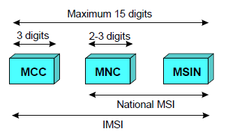
The International Mobile Subscriber Identity (IMSI) is a unique identity allocated to each subscriber that facilitates correct subscriber identification over the radio path and through the network. It is used for all signaling in the PLMN. All network related subscriber information is connected to an IMSI. TheIMSI is stored in the SIM, the HLR and in the serving VLR. The IMSI consists of three different parts:
IMSI
MCC Mobile Country Code
MNC Mobile Network Code
MSIN Mobile Station Identification Number
According to the GSM specifications, the IMSI has a maximum length of 15 digits.
Temporary Mobile Subscriber Identity (TMSI)
The Temporary Mobile Subscriber Identity (TMSI) is a temporary IMSI number made known to an MS at registration. It is used to protect the subscriber's identity on the air interface. The TMSI has local significance only (that is, within the MSC/VLR area) and is changed at time intervals or when certain events occur such as location updating. Every operator can chose TMSI structure, but should not consist of more than 8 digits.
EQUIPMENT-RELATED IDENTITIES
International Mobile Equipment Identity (IMEI)
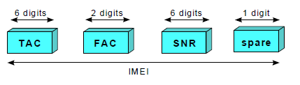
The International Mobile Equipment Identity (IMEI) is used to uniquely identify MS equipment to the network. The IMEI is used for security procedures such as identifying stolen equipment and preventing unauthorized access to the network. According to the GSM specifications, IMEI has a total length of 15 digits, and consists of the following:
IMEI
TAC Type Approval Code, determined by a central GSM body FAC Final Assembly Code, identifies the manufacturer SNR Serial Number, an individual serial number of six digits uniquely identifies all equipment within each TAC and FAC spare A spare digit for future use. When transmitted by the MS this digit should always be zero
International Mobile Equipment Identity and Software Version number
(IMEISV)
The International Mobile Equipment Identity and Software Version number (IMEISV) provides a unique identity for every MS and also refers to the version of software which is installed in the MS. The version of software is important as it may affect the services offered by the MS or its speech coding capabilities. For example, mobile networks need to know the MS speech coding capabilities when a call is being made (i.e. half rate/full rate, etc). This will be indicated by the IMEISV. The IMEISV consists of the following:
IMEISV
SVN Software Version Number allows the mobile equipment manufacturer to identify different software versions of a given type approved mobile. SVN value 99 is reserved for future use – 182 – EN/LZT 123 3321 R3B
International Mobile Equipment Identity and Software Version number
(IMEISV)
The International Mobile Equipment Identity and Software Version number (IMEISV) provides a unique identity for every MS and also refers to the version of software which is installed in the MS. The version of software is important as it may affect the services offered by the MS or its speech coding capabilities. For example, mobile networks need to know the MS speech coding capabilities when a call is being made (i.e. half rate/full rate, etc). This will be indicated by the IMEISV. The IMEISV consists of the following:
IMEISV
SVN Software Version Number allows the mobile equipment manufacturer to identify different software versions of a given type approved mobile. SVN value 99 is reserved for future use
LOCATION-RELATED IDENTITIES
Mobile Station Roaming Number (MSRN)
The Mobile Station Roaming Number (MSRN) is a temporary network identity which is assigned during the establishment of a call to a roaming subscriber. More information about the use of MSRN can be found in the "Traffic Cases" section later in the book. The MSRN consists of three parts:
MSRN
Note: In this case, SN is the address to servicing MSC/VLR.
SN= Servicing Node
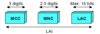
Location Area Identity (LAI)
The Location Area Identity (LAI) is a temporary network identity, which is also required for routing. The two main purposes of the LAI are:
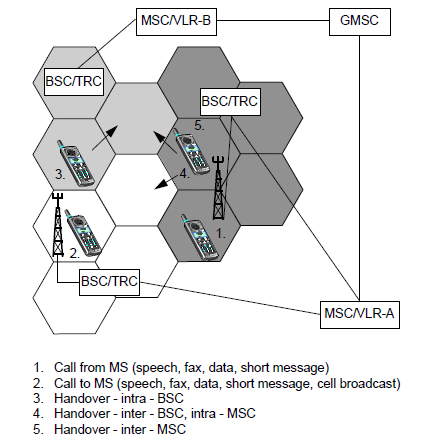
1. Paging, which is used to inform the MSC of the LA in which the MS is currently situated
2. Location updating of mobile subscribers The LAI contains the following:
LAI
LAC Location Area Code, the maximum length of LAC is 16 bits, enabling 65,536 different location areas to be defined in one PLMN
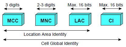
Cell Global Identity (CGI)
The Cell Global Identity (CGI) is used for identifying individual cells within a LA. Cell identification is achieved by adding a Cell Identity (CI) to the LAI components. The CI has a maximum length of 16 bits. The CGI consists of:
CGI
Base Station Identity Code (BSIC)
The Base Station Identity Code (BSIC) enables MS's to distinguish between different base stations sending on the same frequency. The BSIC consists of:
BSIC
NCC Network Color Code (3 bits) identifies the PLMN. Note that it does not uniquely identify the operator. NCC is primarily used to distinguish between operators on each side of a border BCC Base Station Color Code (3 bits) identifies the Base Station to help distinguish between RBS using the same control frequencies
Location Number (LN)
The Location Number (LN) is a number related to a certain geographical area, which the network operator specifies by “tying” the location numbers to cells, location areas, or MSC/VLR service areas. The LN is used to implement features like regional/local subscription and geographical differentiated charging. The LN consists of the following:
LN
LSP Locally Significant Part
Regional Subscription Zone Identity (RSZI)
For each regional subscription, zones/regions need to be defined. This is achieved by using the Regional Subscription Zone Identity (RSZI). The RSZI consist of the following:
RSZI
ZC The length of the Zone Code, is two octets
SUBSCRIBER IDENTITY CONFIDENTIALITY
Subscriber identity confidentiality means that the IMSI is not disclosed to unauthorized individuals, entities or processes. This function protects a subscriber’s identity when the subscriber is using PLMN resources. It also prevents tracing the mobile subscriber’s location by listening to the signaling exchanges on the radio path.
Subscriber Identity Confidentiality Procedure
Each time a mobile station requests a system procedure (e.g. location updating, call attempt or service activation), the MSC/VLR can allocate a new TMSI to an IMSI. The MSC/VLR transmits the TMSI to MS that stores it on the SIM card. Signaling between MSC/VLR and MS utilizes only the TMSI from this point on. Thus, the real subscriber identity, IMSI, is not transmitted over the radio path again. TMSI is half the length of IMSI; thus allowing twice as many MS's to be paged in the same paging message.IMSI is only used in cases when location updating fails or when the MS has no allocated TMSI.