Many problems may occur during the transmission of a radio signal. Some of the most common problems are described below.
PATH LOSS
Path loss occurs when the received signal becomes weaker and weaker due to increasing distance between MS and BTS, even if here are no obstacles between the transmitting (Tx) and receiving (Rx) antenna. The path loss problem seldom leads to a dropped call because before the problem becomes extreme, a new transmission path is established via another BTS.
SHADOWING
Shadowing occurs when there are physical obstacles including hills and buildings between the BTS and the MS. The obstacles create a shadowing effect which can decrease the received signal strength. When the MS moves, the signal strength fluctuates depending on the obstacles between the MS and BTS. A signal influenced by fading varies in signal strength. Drops in strength are called fading dips.
Shadowing
MULTIPATH FADING
Multipath fading occurs when there is more than one transmission path to the MS or BTS, and therefore more than one signal is arriving at the receiver. This may be due to buildings or mountains, either close to or far from the receiving
device. Rayleigh fading and time dispersion are forms of multipath fading.
Rayleigh fading
This occurs when a signal takes more than one path between the MS and BTS antennas. In this case, the signal is not received on a line of sight path directly from the Tx antenna. Rather, it is reflected off buildings, for example, and is received from several different indirect paths. Rayleigh fading occurs when the obstacles are close to the receiving antenna.
Rayleigh fading
The received signal is the sum of many identical signals that differ only in phase (and to some extent amplitude). A fading dip and the time that elapses between two fading dips depends on both the speed of the MS and the transmitting frequency. As an approximation, the distance between two dips caused by Rayleigh fading is about half a wavelength. Thus, for GSM 900 the distance between dips is about 17 cm.
Time Dispersion
Time dispersion is another problem relating to multiple paths to the Rx antenna of either an MS or BTS. However, in contrast to Rayleigh fading, the reflected signal comes from an object far away from the Rx antenna. Time dispersion causes Inter-Symbol Interference (ISI) where consecutive symbols (bits) interfere with each other making it difficult for the receiver to determine which symbol is the correct one. An example of this is shown in the figure below where the sequence 1, 0 is sent from the BTS.
Time dispersion
If the reflected signal arrives one bit time after the direct signal, then the receiver detects a 1 from the reflected wave at the same time it detects a 0 from the direct wave. The symbol 1 interferes with the symbol 0 and the MS does not know which one is correct.
TIME ALIGNMENT
Each MS on a call is allocated a time slot on a TDMA frame. This is an amount of time during which the MS transmits information to the BTS. The information must also arrive at the BTS within that time slot. The time alignment problem occurs when part of the information transmitted by an MS does not arrive within the allocated time slot. Instead, that part may arrive during the next time slot, and may interfere with information from another MS using that other time slot. A large distance between the MS and the BTS causes time alignment. Effectively, the signal cannot travel over the large distance within the given time.
The time alignment problem
For example, an MS is close to a BTS and has been allocated time slot 3 (TS 3). During the call, the MS moves away from the BTS causing the information sent from the BTS to arrive at the MS later and later. The answer from the MS also arrives later at the BTS. If nothing is done, the delay becomes so long that the transmission from the MS in time slot 3 overlaps with the information which the BTS receives in time slot 4.
COMBINED SIGNAL LOSS
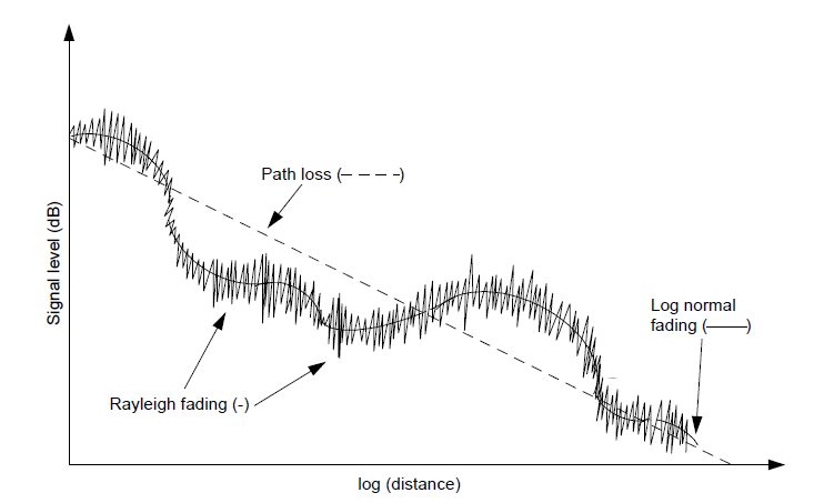
Each of the problems described above occurs independently of each other. However, in most calls some of these problems may occur at the same time. An illustration of what the signal strength may look like at the MS Rx antenna when moving away from the BTS Tx antenna is shown in Figure. The problems of path loss, shadowing and Rayleigh fading are present for this transmission path. The signal strength as a global mean value decreases with the distance (path loss) and finally results in a lost connection. Around this global mean, slow variations are present due to shadowing effects and fast variations are present due to Rayleigh fading.
Rx signal strength versus distance
At any one point from the Tx antenna, the received signal can look like the signal in Figure below.
Rx signal strength
The lowest signal strength value required for a specified output is called receiver sensitivity level. To detect the information sent from Tx antenna, X watts must be received. If the signal falls below X, the information will be lost and the call may be dropped. To ensure that no information is lost, the global mean value must be as many dB above the receiver sensitivity level as the strongest (deepest) fading dip gives rise to. This fading margin is the difference between the global mean value and the receiver sensitivity.


0 comments:
Post a Comment