RBS INTRODUCTION
An RBS includes all radio and transmission interface equipment needed on site to provide radio transmission for one or several cells. The RBS 2000 family is Ericsson's second generation of RBS offering products with a low total lifetime cost1. This is achieved by functions including long Mean Time Between Failure (MTBF) performance and short Mean Time To Repair (MTTR). In addition, this product line is quick and easy to install thus giving the possibility to achieve a rapid network roll out. RBS 2000 provides products for both indoor and outdoor installations and is available for GSM 900, GSM 1800 and GSM 1900.

Examples of the RBS 2000 series
RBS FUNCTIONS
RBS functionality can be divided into the following areas:
• Radio resources
• Signal processing
• Signaling link management
• Synchronization
• Local maintenance handling
• Functional supervision and testing
Radio Resources
An RBS's main function is to provide connection with the MSs over the air interface. This includes the following tasks:
• Configuration and system start:
Site configuration involves loading of software from the BSC and setting parameters prior to system startup, including:
− Transmitter and receiver frequencies
− Maximum output power
− Base Station Identity Code (BSIC)
• Radio transmission:
To transmit several frequencies using the same antenna, a combiner or a set of combiners are needed. Transmission power is controlled from the BSC.
• Radio reception:
In addition to reception of traffic on the physical channels, a primary RBS function the detection of channel requests from MSs (e.g. when a call is being made).

The RBS listening for channel requests and
measuring the uplink on an established connection
Signal Processing
An RBS is responsible for the processing of signals before transmission and after reception. This includes:
• Ciphering using the ciphering key
• Channel coding and interleaving
• Adaptive equalization
• Realization of diversity
• Demodulation
Signaling Link Management
An RBS manages the signaling link between the BSC and MS, applying the appropriate protocols to the information being sent.
Synchronization
Timing information is extracted from the PCM-links from the BSC and is sent to a timing module within the RBS. That enable the RBS to synchronize with the correct frequency reference and TDMA frame number.
Local Maintenance Handling
An RBS enables operation and maintenance functions to be carried out locally at the RBS site, without BSC connection. In this way, field technicians can maintain RBS equipment and software on site.
Functional Supervision and Testing
Supervision and testing of RBS functions is supported, using either built-in tests during normal operation or tests executed by command.
RBS 2000 IMPLEMENTATION
All types of RBS within the RBS 2000 series have the following characteristics:
• Support for user flexibility by providing modular hardware and software designs.
• Transceiver oriented design, which stresses using as little common equipment as possible ensuring dependable performance.
• Design and use are aimed at keeping system life cycle costs low.
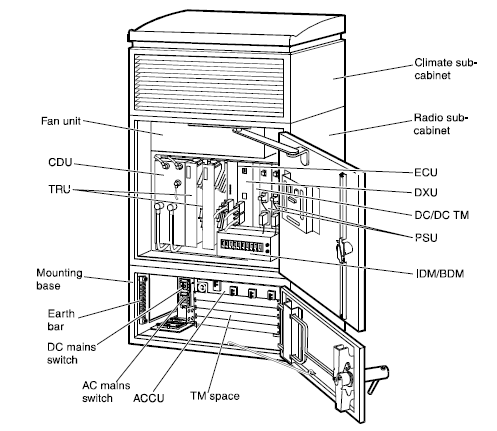
The RBS 2000 series is based on standardized hardware units called Replaceable Units (RU). The major RU’s are:
• Distribution switch Unit (DXU)
• TRansceiver Unit (TRU)
• Combining and Distribution Unit (CDU)
• Power Supply Unit (PSU)
• Energy Control Unit (ECU)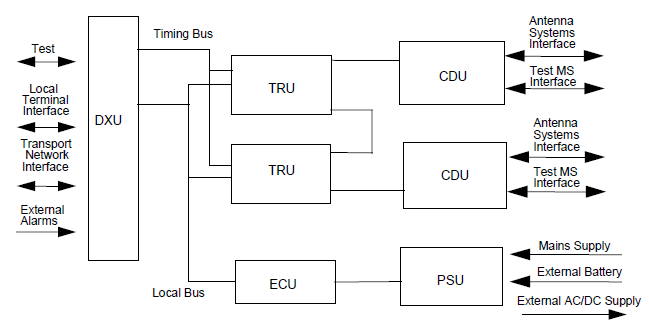
Replaceable units in RBS 2000
Distribution switch Unit (DXU)
The DXU performs the following tasks:
• Provides an interface to the BSC
• Manages the link resources and connects the traffic time slots from the BSC link to the TRU’s
• Controls signaling to the BSC and performs concentration
• Extracts synchronization information from the link and generates a timing reference for the RBS In addition, the DXU has a database which stores information about installed hardware.
TRansceiver Unit (TRU)
One TRU includes all functionality needed for handling one radio carrier (i.e. the 8 time slots in one TDMA frame). It is responsible for radio transmitting, radio receiving, power amplification and signal processing. The TRU contains a radio frequency test loop between the transmitter and the receiver. This facilitates TRU testing by generating signals and looping them back. TRU’s are connected by a bus to enable frequency hopping. Some RBS products can contain up to 6 TRUs.
Combining and Distribution Unit (CDU)
The CDU is the interface between the TRUs and the 2-way antenna system. The task of the CDU is to combine signals to be transmitted from various transceivers and to distribute received signals to the receivers. All signals are filtered before transmission and after reception using bandpass filters. A range of CDU types have been developed to support different configurations within the RBS 2000 family. They consist of different types of CDUs, including:
• Without combiners
• With hybrid combiners
• With filter combiners to support large configurations
CDUs with duplex filters make it possible to transmit and receive using the same antenna.
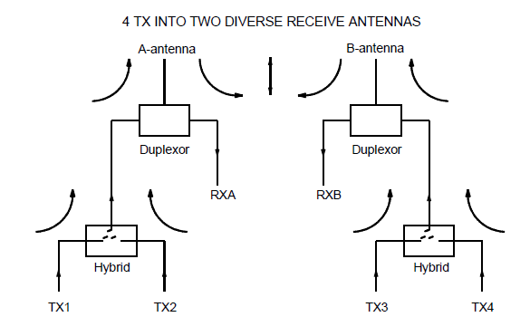
Example of a CDU type C
Power Supply Unit (PSU)
The PSU rectifies the power supply voltage to the +24 VDC necessary for RBS operation.
Energy Control Unit (ECU)
The ECU controls and supervises the power equipment and regulates the environmental conditions inside the cabinet. The RBS 2000 is pre-assembled at the factory including program load and parameter settings making a quick startup possible. Assembly can also be carried out on site. The RBS software isdownloaded from the BSC and stored in a non-volatile (flash memory) program store. In a working RBS, this flash memory keeps cell down time low because traffic does not need to be interrupted. Power failure recovery can also be done quickly.
RBS 2000 IN A NETWORK
The Transmission Drop and Insert (TDI) function makes it possible to connect RBS’s together. This is an important cost saving feature of Ericsson’s RBS’s, as an RBS need not be connected to the BSC directly via a dedicated link. Instead it may be more economic to connect that RBS to another RBS in the region, thus saving on expensive transmission costs. The following network topologies are supported:
• Star:
This is the traditional architecture, where each RBS is connected directly to a BSC
• Cascade:
A cascade architecture includes RBS’s connected to each other without a loop, thus using transmission resources efficiently
• Loop:
This architecture includes RBSs connected to each other with a loop, ensuring that even if one link fails, another path is available

Ericsson’s RBS 2000 Network Configurations
RBS 2000 SERIES DESCRIPTIONS

RBS 2000 Series
RBS 2101

RBS 2102

RBS 2103

RBS 2202

RBS 2301. RBS 2302 is almost identical
(h)
ReplyDeletethank you
ReplyDeletes
ReplyDeleteThis comment has been removed by the author.
ReplyDeleteHello,
ReplyDeleteYour blog have very informative content, its very useful for me. I make a project of Cellular Antenna, this blog include knowledgeable data. Click below.
Cellular Antenna Manufacturers